
Airwell Water Source Heat Pump Error Codes
Airwell Water Source Heat Pump Error Codes
Meanings of Error Code for Line Controller
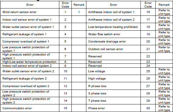
- Wind return sensor error 1 1 Antifreeze indoor coil of system 1 16 Refer to unit type
- Indoor coil sensor error of system 1 2 Antifreeze indoor coil of system 2 17 Refer to unit type
- Water outlet sensor error of system 1 3 Low temperature heating prohibited 18 Refer to unit type
- Refrigerant leakage of system 1 4 Water flow switch error 19 Refer to unit type
- Compressor overload of system 1 5 Condensate drainage error 20 Refer to unit type
- Low pressure switch protection of system 1
- 6 Outdoor coil sensor error 21 Refer to unit type
- High pressure switch protection of system 1 7 Reserved 22
- High/Low water temperature protection 8 Reserved 23
- Indoor coil sensor error of system 2 9 Reserved 24
- Water outlet sensor error of system 2 10 Low voltage 25 Refer to unit type
- Refrigerant leakage of system 2 11 High voltage 26 Refer to unit type
- Compressor overload of system 2 12 R phase loss 27 Refer to unit type
- Low pressure switch protection of system 2 13 S phase loss 28 Refer to unit type
- High pressure switch protection of system 2 14 T phase loss 29 Refer to unit type
- Communication error 15 Phase error 30 Refer to unit type.
Airwell Maintenance and Servicing Dubai
- Normal maintenance of the appliances is generally limited to replacing filters.
- The filters must be changed at regular intervals. The frequency is dependent on the specific application conditions. Certain installations, for example in hotels where there large amounts of fluff due to the frequent bedding changes and the presence of fitted carpets, require more frequent filter changes. It is recommended that the filters are checked every 60 days during the first year of operation in order to determine the frequency required. If it is not possible to see light through the filter when it is held up to the sun or in front of a strong light, the filter must be replaced. A more rigorous standard of cleanliness may be required.
- The condensates tray must be checked annually and cleaned and rinsed if necessary.
- On commissioning, a record of voltages, current draw and temperature variances should be made. Thereafter, on an annual basis further measurements can be compared to these initial values and will be useful for giving an overall indication for the equipment’s general condition.
- The activation of the unit’s safety protection devices is usually caused by air or water problems. These forced stoppages are a normal protection measure. Ensure that there is no dirt or debris in the air or water circuits. Check the water and air temperatures and flows (clogged filters).
Leave a Reply
Want to join the discussion?Feel free to contribute!